Inserting Sequence Diagram Elements
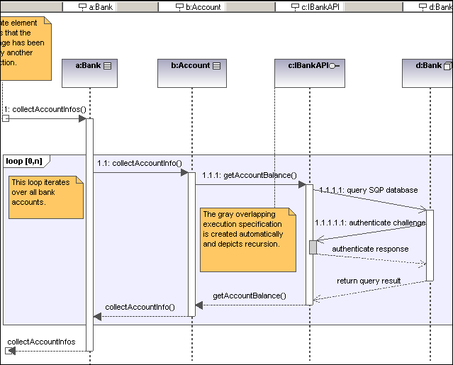
A sequence diagram models runtime dynamic object interactions, using messages. Sequence diagrams are generally used to explain individual use case scenarios.
•Lifelines are the horizontally aligned boxes at the top of the diagram, together with a dashed vertical line representing the object's life during the interaction. Messages are shown as arrows between the lifelines of two or more objects.
•Messages are sent between sender and receiver objects, and are shown as labeled arrows. Messages can have a sequence number and various other optional attributes: argument list etc. Conditional, optional, and alternative messages are all supported.
See also:
•Gate
Sequence diagram and other UModel elements, can be inserted into a sequence diagram using several methods.

Using the toolbar icons
1.Click the specific sequence diagram icon in the Sequence Diagram toolbar.
2.Click in the Sequence diagram to insert the element. To insert multiple elements of the selected type, hold down the Ctrl key and click in the diagram window.
Dragging existing elements into the sequence diagram
Most classifier types, as well as elements occurring in other sequence diagrams, can be inserted into an existing sequence diagram.
1.Locate the element you want to insert in the Model Tree tab (you can use the search function text box, or press Ctrl+F to search for any element).
2.Drag the element(s) into the sequence diagram.