Internal Block Diagram
Internal Block Diagrams are based on the UML Composite Structure Diagrams, with restrictions and extensions as defined by SysML. The Internal Block Diagram describes the internal structure of a block and connections between its constituent parts, using ports, connectors, and flows. The typical way to create a new Internal Block Diagram is as follows:
•Right-click an existing block in the Model Tree and select New Diagram | SysML Internal Block Diagram from the context menu.
If you create a new Internal Block Diagram without right-clicking an existing block first, a new block is created as well in the Model Tree, and the new diagram is nested under the block because it is assumed to describe it. For example, in the model illustrated below, the "CardReader" diagram describes the "SampleATM" block.
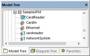
The "CardReader" diagram is available in the following demo project: C:\Users\<username>\Documents\Altova\UModel2026\UModelExamples\Bank_SysML.ump.
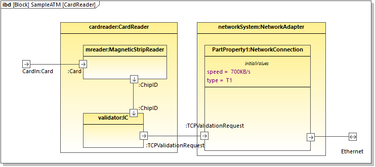
CardReader diagram
The cardreader and networksystem properties illustrated above have the type CardReader and NetworkAdapter, respectively. These types exist in the same model and are blocks, which determines the appearance of properties in the diagram. Note that you can set or change the type of a property from the type drop-down list in the Properties Window.
Initial values
When a property has a type that is a "block" like in this example, it can be created with initial values. For example, the property PartProperty1 in the CardReader diagram has the initial value of speed = 700KB/s.
To add initial values to a property:
1.Right-click the property and select New | Initial Values.
2.Double-click the placeholder and enter the values (for example, speed = 700KB/s).
Standard ports
To add a standard port, click the Port ![]() toolbar button and then click on the diagram. The port is now added to the diagram.
toolbar button and then click on the diagram. The port is now added to the diagram.
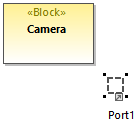
To attach the port to a block, drag it over the border of the block ("Camera", in this example) and drop it when the border becomes highlighted. The port is now attached to the border of the block.
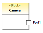
To change the port's name and type, first select the port on the diagram, and then change the name and type properties of the Properties Window.
Flow ports
To create a flow port, click the FlowPort ![]() toolbar button, and then click the border of a block. The flow port is now attached to the border of the block. You can also create and attach flow ports in two separate steps, as shown above for standard ports.
toolbar button, and then click the border of a block. The flow port is now attached to the border of the block. You can also create and attach flow ports in two separate steps, as shown above for standard ports.
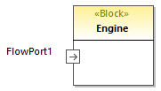
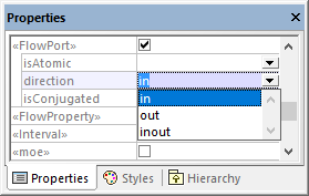
You can change the port's name and type by editing the respective properties in the Properties window. Note that flow ports have additional properties in the Properties window that let you specify the direction, for example (in, out, inout).
To create an atomic conjugated flow port:
1.Create a FlowSpecification (interface) in a Block Definition Diagram (BDD).
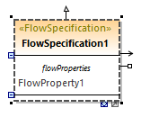
2.Click the flow port in the Internal Block Diagram (IBD).
3.In the Properties window, set the type property to the FlowSpecification created earlier.
4.In the Properties window, set the isConjugated property to true.
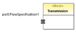
An atomic conjugated port is shown with a dark background.
Joining ports
You can join two ports as follows:
1.Click the Connector  toolbar button.
2.Drag and drop from the first to the second port.
3.Drop the connector on the port, when the port object is highlighted in the diagram.
Item flows
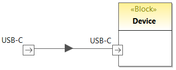
Item flows can be created between block associations, or on other connectors between parts of SysML diagrams.
To create item flows, right-click an existing connector and select New | Item flow (left to right, or right to left) from the context menu. An arrowhead is added to the connector, displaying the direction of the item flow.
Proxy ports and direction
In newer versions of SysML, proxy ports can show direction, similar to flow ports of older SysML versions. For example, the diagram illustrated below consists of a block ("Antenna") with two proxy ports that show direction.
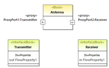
Here is an example of how to add direction to proxy ports:
1.Add a block and two interface blocks to the diagram. In the example above, the block is "Antenna" and the two interface blocks are "Transmitter" and "Receiver".
2.Select the "Transmitter" and press F7 to add a new flow property to it.
3.Add a proxy port to the block and change its type to "Transmitter" from the Properties window.
4.Select the flow property on the diagram and, from the Properties window, change the direction property to out. Notice that the direction of the proxy port changes to reflect this fact.
5.Select the "Receiver" and press F7 to add a new flow property to it.
6.Add a second proxy port to the block and change its type to "Receiver" from the Properties window.
7.Select the flow property on the diagram and, from the Properties window, change the direction property to in. Again, the direction of the proxy port changes to reflect this fact.