Aligning and Resizing Modeling Elements
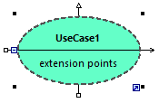
You can change the size of elements on the diagram as follows:
1.Click an element on the diagram. A set of black dots appear at the element's edges.

2.Drag any of the black dots into the direction where you want the element to grow.
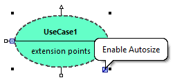
To reset the element size to its default boundaries, do one of the following:
•Click the Enable Autosize icon at the lower-right corner of the element.

•Right-click an element on the diagram, and select Autosize from the context menu.
•Select one or more elements. On the Layout menu, click Autosize.
When at least two modeling elements are selected on the diagram, they can be aligned in relation to each other (for example, both can be aligned to have the same horizontal or vertical position, or even size). The commands which align or resize elements are available in the Layout menu and in the Layout toolbar.
Layout toolbar
When you select several elements, the element that was selected last serves as a template for the subsequent align or resize commands. For example, if you select three class elements and run the Make same width command, then all three will be made as wide as the last class you selected. The element that was selected last always appears with a dashed border. |
The commands specific to element alignment and resizing are as follows:
Icon | Command | Notes |
|---|---|---|
Align left | ||
Align right | ||
Align top | ||
Align bottom | ||
Center vertically | ||
Center horizontally | ||
Space across | This command is available when three or more elements are selected. It distributes the horizontal space evenly between selected elements. | |
Space down | This command is available when three or more elements are selected. It distributes the vertical space evenly between selected elements. | |
Line up horizontally | This command repositions all selected elements on the diagram so that they are arranged horizontally one after the other. | |
Line up vertically | This command repositions all selected elements on the diagram so that they are arranged vertically one after the other. | |
Make same width | ||
Make same height | ||
Make same size |
You can also automatically layout all elements in the diagram, as follows:
•On the Layout menu, click Autolayout All and choose one of the following options: Force Directed, Hierarchic, or Block.
Force Directed | Displays the modeling elements from a centric viewpoint. |
Hierarchic | Displays elements according to their hierarchical relationships. For example, a superclass will be placed above any of its derived classes.
The hierarchical layout options can be customized from the Tools | Options menu, View tab, Autolayout Hierarchic group. |
Block | Displays elements grouped by element size in rectangular fashion. |