Timing Diagram
Altova website:  UML Timing diagrams
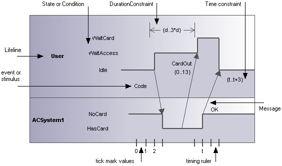
Timing diagrams depict the changes in state, or condition, of one or more interacting objects over a given period of time. States, or conditions, are displayed as timelines responding to message events, where a lifeline represents a Classifier Instance or Classifier Role.
A Timing diagram is a special form of a sequence diagram. The difference is that the axes are reversed i.e. time increases from left to right, and lifelines are shown in separate vertically stacked compartments.
Timing diagrams are generally used when designing embedded software or real-time systems.

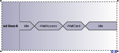
There are two different types of timing diagram: one containing the State/Condition timeline as shown above, and the other, the General value lifeline, shown below.
