Activity Diagram elements
 Action (CallBehavior)
Inserts a CallBehaviorAction element which directly invokes a specific behavior. Selecting an existing behavior using the behavior combo box, e.g. HandleDisplayException, displays a rake symbol within the element.

Inserts a CallOperationAction which indirectly invokes a specific behavior as a method. Please see "Inserting an action (CallOperation)" for more information.

A type of action used to specify implementation information. Can be used as a placeholder until you decide which specific action type you want to use.
A type of action that evaluates(/generates) a specific value at the output pin. (Defined by the specific properties, e.g. upperBound.)
Inserts the Accept Event action which waits for the occurrence of an event which meets specific conditions.
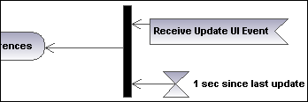
Inserts an AcceptEventAction, triggered by a time event, which specifies an instant of time by an expression e.g. 1 sec. since last update.
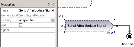
Inserts the SendSignalAction, which creates a signal from its inputs and transmits the signal to the target object, where it may cause the execution of an activity.
Inserts a Decision Node which has a single incoming transition and multiple outgoing guarded transitions. Please see "Creating a branch" for more information.
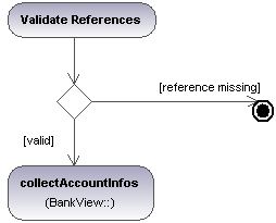
Inserts a Merge Node which merges multiple alternate transitions defined by the Decision Node. The Merge Node does not synchronize concurrent processes, but selects one of the processes.
The beginning of the activity process. An activity can have more than one initial node.
The end of the activity process. An activity can have more that one final node, all flows in the activity stop when the "first" final node is encountered.
Inserts the Flow Final Node, which terminates a flow. The termination does not affect any other flows in the activity.
Inserts a vertical Fork node. Used to divide flows into multiple concurrent flows.
Inserts a horizontal Fork node. Used to divide flows into multiple concurrent flows.
Inserts a vertical Fork node. A Join node synchronizes multiple flows defined by the Fork node.
Inserts a horizontal Fork node. A Join node synchronizes multiple flows defined by the Fork node.
Inserts an input pin onto a Call Behavior, or Call Operation action. Input pins supply input values that are used by an action. A default name, "argument", is automatically assigned to an input pin.

The input pin symbol can only be placed onto those activity elements where the mouse pointer changes to the hand symbol ![]() . Dragging the symbol repositions it on the element border.
. Dragging the symbol repositions it on the element border.
Inserts an output pin action. Output pins contain output values produced by an action. A name corresponding to the UML property of that action e.g. result, is automatically assigned to the output pin.
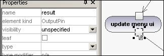
The output pin symbol can only be placed onto those activity elements where the mouse pointer changes to the hand symbol  . Dragging the symbol repositions it on the element border.
Exception Pin
An OutputPin can be changed to an Exception pin by clicking the pin and selecting "isExceptionPin" from the Properties pane.
Inserts a Value Pin which is an input pin that provides a value to an action, that does not come from an incoming object flow. It is displayed as an input pin symbol, and has the same properties as an input pin.
 ObjectNode
Inserts an object node which is an abstract activity node that defines object flow in an activity. Object nodes can only contain values at runtime that conform to the type of the object node.
Inserts a Central Buffer Node which acts as a buffer for multiple in- and out flows from other object nodes.
Inserts a Data Store Node which is a special "Central Buffer Node" used to store persistent (i.e. non transient) data.
Inserts a horizontal Activity Partition, which is a type of activity group used to identify actions that have some characteristic in common. This often corresponds to organizational units in a business model.
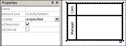
Double clicking a label allows you to edit it directly; pressing Enter orients the text correctly.
Please note that Activity Partitions are the UML 2.0 update to the "swimlane" functionality of previous UML versions.
•Elements placed within a ActivityPartition become part of it when the boundary is highlighted.
•Objects within an ActivityPartition can be individually selected using Ctrl+Click, or by dragging the marquee inside the boundary.
•Click the ActivityPartition boundary, or title, and drag to reposition it.
Inserts a vertical Activity Partition, which is a type of activity group used to identify actions that have some characteristic in common. This often corresponds to organizational units in a business model.
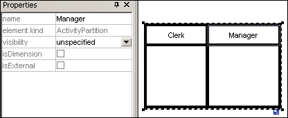
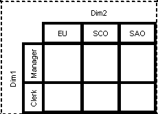
Inserts a two dimensional Activity Partition, which is a type of activity group used to identify actions that have some characteristic in common. Both axes have editable labels.
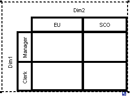
To remove the Dim1, Dim2 dimension labels:
1.Click the dimension label you want to remove e.g. Dim1
2.Double click in the Dim1 entry in the Properties tab, delete the Dim1 entry, and press Enter to confirm.
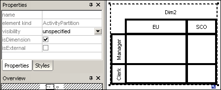
Note that Activity Partitions can be nested:
1.Right click the label where you want to insert a new partition.
2.Select New | ActivityPartition.
A Control Flow is an edge, i.e. an arrowed line, that connects two activities/behaviours, and starts an activity after the previous one has been completed.

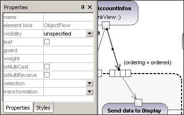
A Object Flow is an edge, i.e. an arrowed line, that connects two actions/object nodes, and starts an activity after the previous one has been completed. Objects or data can be passed along an Object Flow.
An Exception Handler is an element that specifies what action is to be executed if a specified exception occurs during the execution of the protected node.
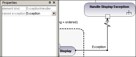
An Exception Handler can only be dropped on an Input Pin of an Action.
Inserts an Activity into the activity diagram.
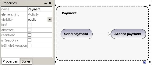
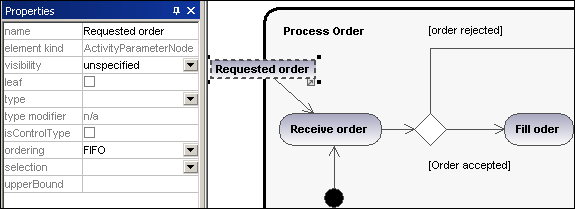
Inserts an Activity Parameter node onto an activity. Clicking anywhere in the activity places the parameter node on the activity boundary.
Inserts a Structured Activity Node which is a structured part of the activity, that is not shared with any other structured node.

An expansion region is a region of an activity having explicit input and outputs (using ExpansionNodes). Each input is a collection of values.
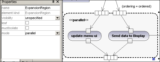
The expansion region mode is displayed as a keyword, and can be changed by clicking the "mode" combo box in the Properties tab. Available settings are:parallel, iterative, or stream.
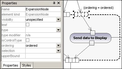
Inserts an Expansion Node onto an Expansion Region. Expansion nodes are input and output nodes for the Expansion Region, where each input/output is a collection of values. The arrows into, or out of, the expansion region, determine the specific type of expansion node.
An interruptible region contains activity nodes. When a control flow leaves an interruptible region all flows and behaviors in the region are terminated.
To add an interrupting edge:
1.Make sure that an Action element is present in the InterruptableActivityRegion, as well as an outgoing Control Flow to another action:

2.Right click the Control Flow arrow, and select New | InterruptingEdge.

Note: You can also add an InterrupingEdge by clicking the InterruptableActivityRegion, right clicking in the Properties window, and selecting Add InterruptingEdge from the pop-up menu.